| HYGBG02 | |||||||
|---|---|---|---|---|---|---|---|
| Antenna Dimensions | 50 x 50 x 14 (mm) | 36 x 36 x 8.5 (mm) | |||||
| Low band Gain | 2.0dBi | 0dBi | |||||
| Low band Axial ratio | 2.0dB | 2.0dB | |||||
| High band Gain | 2.7dBi | 0.5dBi | |||||
| High band Axial ratio | 2.0dB | 2.0dB | |||||
| Weight | 22g | 10g | |||||
| Connector | on-board direct feed or cable with IPEX | ||||||
| Phase center error | <2.0 mm | ||||||
| Input impedance | 50Ω | ||||||
| VSWR | ≦ 3 | ||||||
| LNA Gain | 32dB±2dB | ||||||
| Polarization | RHCP | ||||||
| Temperature | -40℃- +85℃ | ||||||
| Salt spray test | 48H | ||||||
| Air-medium | Ceramic | |
| Weight | 15.6 g | 74.3 g |
| Dimensions | 50 x 50 x 15 mm | 50 x 50 x 14 mm |
| Low Frequency Gain | 2.0 dBi | 1.8 dBi |
| High Frequency Gain | 2.7 dBi | 2.5 dBi |
| Process | Stamping with cooper | Ceramic sintering |
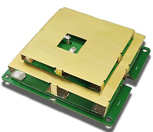
Model number: HYGBG02
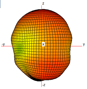
RHCP radiation pattern at 1176MHz
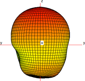
RHCP radiation pattern at 1575MHz
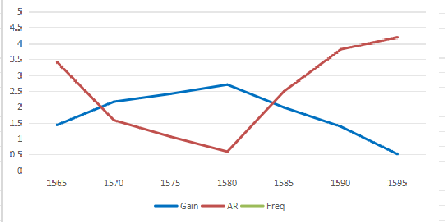
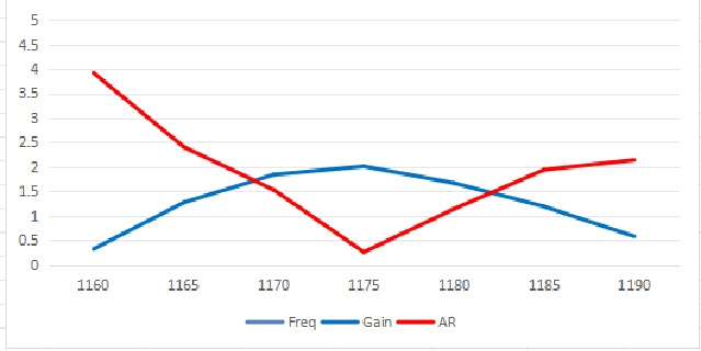
Plot of antenna gain and axial ratio versus frequency